Engineering Prototype Parts: Manufacturing Processes and Applications
Engineering prototypes parts are physical components built to test a design before mass production begins. Makers produce them from CAD files with CNC machining, metal and plastic 3D printing, vacuum casting, or sheet metal fabrication. Each method answers a different question about structure, appearance, assembly, or function. At BOEN Rapid, we turn CAD data into working parts starting from a single piece. Our initial project assessment arrives within 24 hours, and prototype parts ship in 3–15 working days, depending on complexity. This guide covers the main processes, materials, applications, and supplier checks so you can choose the right path for your next build.
Understanding Engineering Prototype Parts
What Engineering Prototype Parts Are?
An engineering prototypes parts is a model of a future production part that works. We use materials and techniques that are good enough for production, which makes it different from a simple model that only shows shape. You can load it, put it together, and test how it works. In their book on product development, Ulrich and Eppinger say that prototypes are used for four things: learning, discussion, merging, and setting goals. All four can be done with engineering prototypes parts. They let a team know if a snap fit works, if a bracket clears a nearby part, and if a housing feels good when you hold it. A production part is added after the design is finalized, and it generally needs its own set of tools.
Functional, Visual, and Fit Prototypes
Here are three groups of prototypes that most of them fit into. A useful engineering prototypes parts needs to be made of a strong material like nylon, aluminum, or stainless steel so it can hold weight, move, seal, or deal with heat. A visible engineering prototypes parts is all about the shape, color, and finish of the surface. Often, finished CNC plastic parts or parts that were vacuum cast can be used for this. A fit engineering prototypes parts checks the details of an assembly, like the distance between holes, the snaps, and the space between parts that fit together. A lot of teams order all three at the same time. The materials come after the goal. Among other things, we work with aluminum, stainless steel, titanium, brass, ABS, PC, nylon, PEEK, and POM. If you choose the right type of engineering prototypes parts for your question, the build will be small and the results will be clear.
Why Prototyping Pays Off Early?
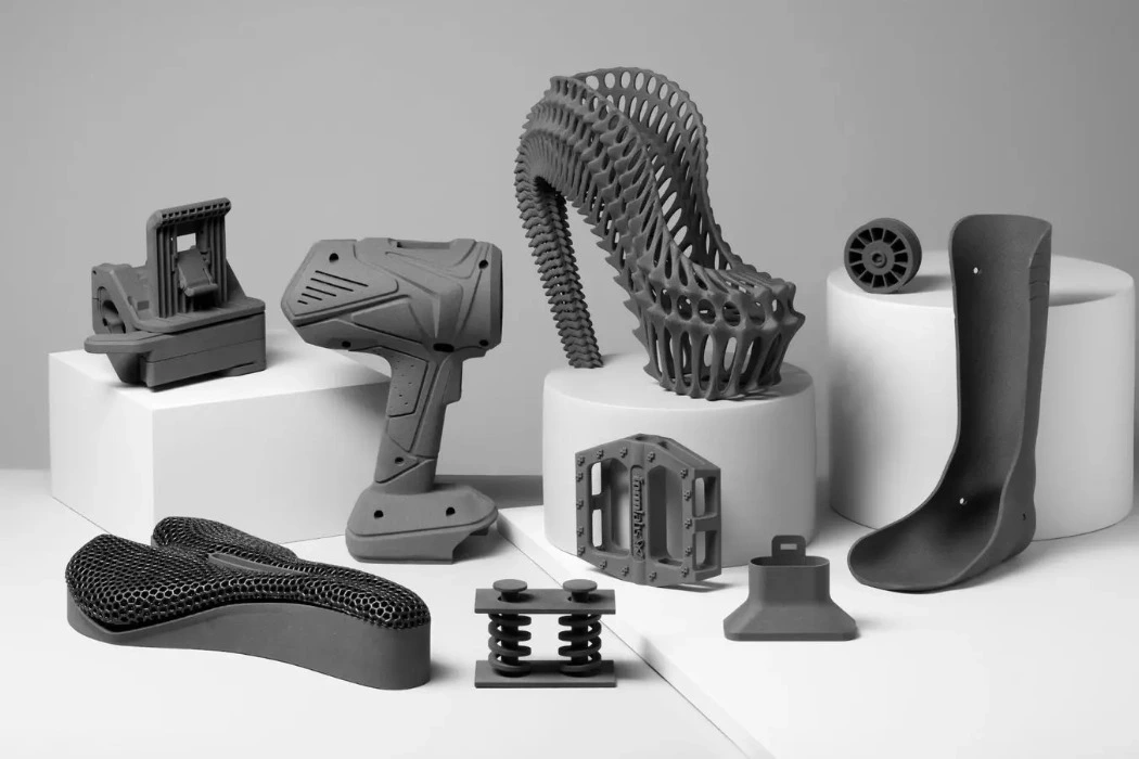
You can find flaws in a engineering prototypes parts for a lot less money than in a production tool. This is something that Boothroyd, Dewhurst, and Knight also talk about in their research on design for manufacture and assembly: decisions made early in the design process lock in a lot of the final cost. Problems that are hidden on screen models can be seen in the real parts, like a screw boss that is too crowded, a thin wall that is warped, or a connector that you can't reach with your hand. Because a team can try several versions of a design within weeks, prototyping also speeds up the development process. For B2B buyers, a validated part also means that the drawings are clearer and there are fewer surprises when the supplier quotes low-volume production.
Manufacturing Processes of Engineering Prototype Parts
CNC Machining, 3D Printing, and Vacuum Casting Compared
Each method is good for a different job. You can see the different methods we use and the lead times we give for each one. CNC machining: 3–7 days for high-precision metal and plastic parts; Metal 3D printing (SLM/DMLS): 5–10 days for complex shapes in titanium, aluminum, and stainless steel; SLS/MJF printing: 3–7 days for functional plastic parts; Vacuum casting: 7–12 days for low-volume plastic parts with a production-like finish; Sheet metal fabrication: 5–10 days for enclosures, brackets, and structural parts;
The surface is clean and the limits are very tight when CNC cutting. When you 3D print metal, you can make inside features that cutting tools can't get to. Because the powder around each layer keeps it in place, SLS can print strong plastic parts without the need for support structures.
From CAD File to Finished Part: Our Workflow
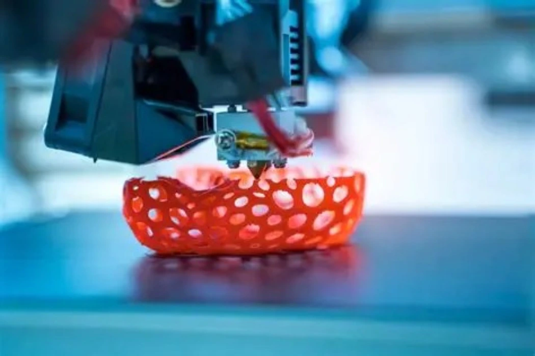
There are five steps in our process. The first thing you do is send a CAD file, usually in STEP format, along with the material and quantity. Second, our engineers look over the model and send you DFM feedback along with the price. Within 24 hours, you'll get the first project assessment. Third, we use the process that works best for your test goal to make the part. Fourth, we make sure that the dimensions and surface finish meet your needs. Fifth, we cushion the part with bubble wrap and send it off by DHL, UPS, or FedEx. Depending on how complicated they are, engineering prototypes parts leave our shop in 3–15 business days. You can switch between methods between design rounds because the same provider does printing, machining, casting, and sheet metal work.
Choosing a Process by Speed, Cost, and Material
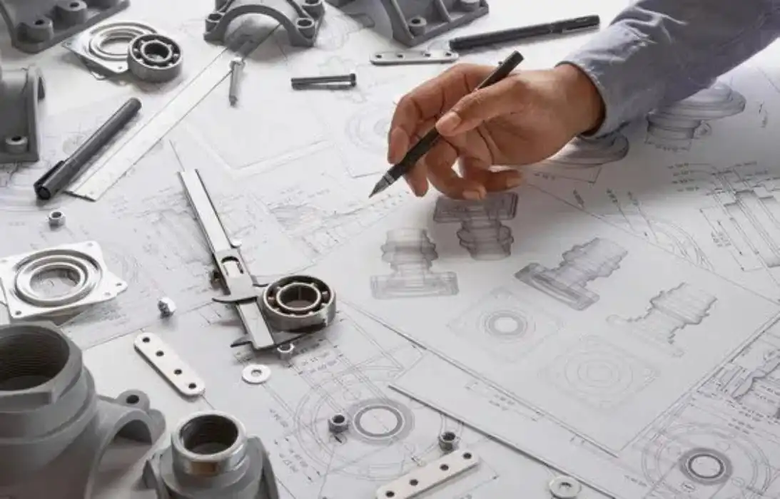
Begin with the question that your test needs to answer. Most of the time, CNC machining is used to make metal parts with very tight tolerances. A complex one-piece shape that is 3D printed often costs less than one that is cut from solid stock. This is because material is only put where it is needed by the shape. A master pattern is copied in a silicone mold so that a small run of plastic housings can have a finish that looks like they were made in a factory. However, each mold has a limited life. On the other side of the road is injection molding. Because it takes steel or aluminum tools, it only makes sense to do it after the plan is set. Let us know what you need, how much, and the goal of the test, and we'll tell you how to do it.
Design and Material Selection Guidelines
Design for Manufacturability Basics
It's better to make good design decisions than bad ones because they save machine time and stop mistakes. A round cutter can't cut a sharp inside edge on CNC parts, so the corners inside need to be rounded. When you have deep, narrow pockets, you need long tools that bend, which makes them less accurate. Thin parts that aren't supported can bend when 3D printed, and hollow designs need a way for powder that gets stuck inside to escape. You can tell if a sheet metal part has a clean flange by its bend radius and hole distance from a bend. Before cutting starts, our engineers mark these points in DFM input so that you can fix a plan instead of throwing away a part. Tight tolerances should only be used when they are needed for the job. Extra precision takes longer to machine and doesn't improve the test.
Choosing Metals and Plastics
If you want to do well on the test, don't just pick things that you know. Stainless steel 304, 316, and 17-4PH can handle corrosion and heavier loads, while aluminum 6061, 7075, and 6082 are good for light structures. Titanium Ti6Al4V is often asked for by aerospace and medical teams because it is strong for its weight and doesn't rust. ABS, PC, and PC-ABS blends are plastics that are used for housings. Nylon PA6, PA12, and PA66 make things tougher, POM makes moving parts less likely to stick, PMMA lets light through, and PEEK and PEI can handle higher temperatures. Material that looks good but doesn't hold up under real load gives false information. We will suggest a grade that fits the operating environment if you tell us what it is.
Prototype Parts vs. Production Parts
Different parts of a production run may have the same design, but not always the same process. Because engineering prototypes parts are made one at a time or in small groups, the finishes may be different from those on plastic parts. There are also different tolerances for each method, so the same feature on a machined part and a molded part may have different sizes. The way things behave changes too. A part that was injection molded has flow lines, but a block that was made does not. We take this worry into account by using materials that are good enough for production. This way, test data stays close to what you can expect in the end. When you move on to tooling, you should measure the first parts' key dimensions again.
Key Applications and Industry Use Cases
Automotive and Aerospace Prototypes
Before they pay for production tooling, automotive teams order internal fixtures, brackets, sensor housings, and engine parts to test in the real world. Within days, a machined aluminum bracket can get to a test vehicle, where the team can check how well it fits with the wiring and other parts nearby. Aerospace teams like titanium and aluminum alloys because they are light and can be used to make structural parts, mounting brackets, and parts of control systems. When a part needs to have internal lines, metal 3D printing can help, and CNC cutting can make surfaces fit together perfectly. In both, a engineering prototypes parts lets engineers check early on how things fit together and how they work mechanically, so changes are made to a drawing instead of a tool. Our processes that are ISO 9001 certified can handle these orders.
Medical Device and Robotics Prototypes
Medical device teams use engineering prototypes parts for surgical instruments, housings for diagnostic equipment, and studies of implants that are unique to each patient. The worldwide standard for managing the quality of medical devices is ISO 13485, and our quality system is certified to that standard. We also offer material certificates and inspection records. In this field, biocompatibility is important. When you choose materials, keep ISO 10993-1's description of biological evaluation as part of a risk management process in mind. Send us your material needs early, and we'll let you know what grade is best. In order to test motion, load, and accuracy, robotics teams order special joints, mounting plates, and end effector parts. Heavy loads can be put on CNC-machined metal, while printed nylon is better for covers and grippers that are lighter.
Consumer Electronics, Industrial Equipment, and Hardware Startups
In just one build cycle, hardware companies and electronics teams often need cases, brackets for the inside, and mounts for connectors. Enclosures and structural parts are made of sheet metal, and vacuum casting gives demos and early user tests a finish that looks like it was made in a factory. Teams that work with industrial equipment order machine parts, tooling fixtures, and automation parts to make sure they will work in real-world situations. Imagine that an engineer sends a housing and a bracket, gets feedback from DFM the next day, and agrees to a mix of CNC and SLS within the lead times given. That's because we already have your file history and finish notes, which are kept safe under an NDA. This means that repeat orders go through faster.

Choosing the Right Supplier for Engineering Prototype Parts
Lead Time, Certifications, and Capabilities
Do three checks first. Ask for a lead time by method first, since the plan for a CNC part and a vacuum cast part are different. It takes us 3–15 working days to make engineering prototypes parts, and 2–4 weeks for low-volume production. Second, look at the licenses. If your product is a medical gadget, ISO 13485 is important. ISO 9001 is for general quality control. We have both. Third, take a look at the capability range. When you buy from a company that does CNC machining, 3D printing, vacuum casting, injection molding, and sheet metal fabrication, you can compare processes fairly since no one method is pushed. Check the dimensions, look at the surface finish, and get inspection reports as well.
IP Protection, Packaging, and Shipping to the United States
It is just as important to protect your design as it is to make the part. Ask each provider if they sign an NDA and how they handle production that is kept secret. We back NDAs and production that is kept secret. We offer custom packaging and ship with DHL, UPS, and FedEx, which all offer door-to-door service and tracking of shipments. This is also true for engineering prototypes parts that are fragile. Engineering prototypes parts that need to be sent quickly can be sent by air, and a tracking number helps your team set a date for the test. It is important to find out how each provider packs thin walls, smooth surfaces, and printed lattices, since damage during shipping can cost a full build cycle.
How to Request and Compare Quotes
A full request gets you a quote faster and more accurately. Send a STEP file, a 2D drawing with important tolerances marked, the material, the amount, and the finish on the surface. It helps our engineers choose the right process if you tell them what your test goal is. When quotes come in, don't just compare the headline number. Check the lead time given, the quality of the DFM notes, the inspection documents that come with the order, and the plan for packaging. A quote that points out a dangerous trait can keep your build from failing. Before going big, make sure the first part is okay, test the important parts, and write down the results. After that, that part is used as a guide for repeat sales and small-scale production.
Conclusion
When engineers make engineering prototypes parts, they can test the structure, look, assembly, and function of a design before committing to making a production tool. This process is different for each question. Metal and plastic parts with tight tolerances can be made with CNC machining, 3D printing can handle complicated shapes, vacuum casting can make small runs of plastic parts with a finish that looks like they were made in a factory, and sheet metal fabrication can make enclosures and brackets. Choose the right material and get early DFM feedback to shape both the test results and the cost of making changes below. Because tolerances, finishes, and the way materials behave can be different, engineering prototypes parts data needs to be checked again on production parts. This is how teams work in the automotive, aircraft, medical, robotics, technology, and industrial fields. The supplier's wait time, certifications, IP protection, and how they package things determine how quickly the testing goes.
FAQ
How long does it take to receive engineering prototype parts?
Lead times depend on how the part is made and how complicated it is. CNC milling and SLS/MJF printing take three to seven days on average. Metal 3D printing and sheet metal fabrication take five to ten days, and vacuum casting takes seven to twelve days. In general, engineering prototypes parts are sent out between 3 and 15 business days. Within 24 hours, we finish the first project evaluation.
How do prototype parts differ from production parts?
Because engineering prototypes parts are only made in small numbers for testing, their details, standards, and how the material behaves may be different from parts that are tooled. For production parts, the plan is set in stone, and special tools are used. We use materials that are good enough for production to make engineering prototypes parts, so the data from your tests will be close to what you expect in the end.
Can I order more than one prototype?
Yes. We start at a single piece and can provide 100 units for long-term testing, and there is no minimum order size. Production of a small amount usually takes two to four weeks. Every order is checked for length, width, and surface finish.
Request Engineering Prototypes Parts from BOEN Rapid
Are you ready to turn your CAD file into a working part? BOEN Rapid is a company that makes engineering prototypes parts. They have been in business for more than 15 years, have methods that are ISO 9001 and ISO 13485 approved, offer DFM feedback, and can deliver in 3–15 working days. Send your drawings to contact@boenrapid.com by email, and within 24 hours, one of our engineers will send you a first evaluation. Find out more at boenrapid.com.
References
1. ISO/ASTM 52900, Additive Manufacturing: General Principles, Fundamentals and Vocabulary, 2021
2. ISO 13485, Medical Devices: Quality Management Systems, Requirements for Regulatory Purposes, 2016
3. ISO 10993-1, Biological Evaluation of Medical Devices, Part 1: Evaluation and Testing Within a Risk Management Process, 2018
4. Gibson, Rosen, and Stucker, Additive Manufacturing Technologies: 3D Printing, Rapid Prototyping, and Direct Digital Manufacturing (Springer), 2015
5. Boothroyd, Dewhurst, and Knight, Product Design for Manufacture and Assembly (CRC Press), 2010
6. Ulrich and Eppinger, Product Design and Development (McGraw-Hill), 2020