5-Axis Machining: Factors that impact accuracy
When engineers and procurement teams specify complex precision components — turbine blades, orthopedic implants, aerospace structural parts — one question consistently comes up: what actually determines whether a finished part meets its tolerance? The answer involves more variables than most buyers expect. Understanding those variables is the first step toward specifying parts correctly and choosing a supplier who can deliver them. This article breaks down the core accuracy factors governing 5-axis machining parts, compares them against conventional approaches, and offers practical guidance for engineering-driven procurement decisions.
Understanding 5-Axis Machining and Accuracy Fundamentals
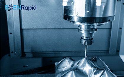
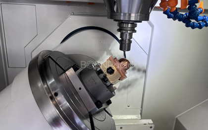
In 5-axis CNC machining, two rotational axes (A and B or A and C) are added to the standard X, Y, and Z axes. This means that the cutting tool can approach a workpiece from almost any angle in a single setup. There is no need to reposition the tool by hand, and there is no buildup of misalignment from using different fixtures.
What "Accuracy" Actually Means in Precision Machining
Three things are used to measure how accurate multi-axis machining is: dimensional tolerance (how close a feature is to its standard value), surface finish (Ra value, usually Ra 0.4–3.2 µm for high-end uses), and repeatability (how consistent the machine is across multiple parts or runs). Tolerances of ±0.005mm are an absolute must for medical and military uses. They are not just a goal.
How Material Properties Influence Achievable Tolerances
What limits can be reached are directly related to how the material behaves under cutting stress. Titanium Grade 5 (Ti-6Al-4V) doesn't have a high modulus of elasticity (about 114 GPa), so parts can bend while being machined if the supports aren't strong enough. Stainless steel 17-4PH hardens quickly when it is worked, so it needs sharp tools and accurate feed rates. Because of these physical facts, the choice of material and the plan for cutting must be made at the same time, not separately.


Why Single-Setup Machining Raises the Accuracy Ceiling
When a part is moved in a 3-axis process, a new number is added, which means there is a new place for error to happen. Studies in precision manufacturing show that single-setup 5-Axis machining part processing cuts positional errors by 30–50% compared to multi-setup operations that do the same thing. This is not a small improvement for cavities, angles, and undercuts that are complicated; it is a big change in what can be done.

Core Factors Impacting the Accuracy of 5-Axis Machining Parts
There is no one setting on a machine that controls accuracy. It is made up of several variables that affect each other and must all be controlled at the same time. The most direct ways to tell if a finished part fits its picture are as follows:
- Machine tool geometry and spindle precision: A 5-axis machine's rotational axes must be calibrated to sub-micron tolerances. Spindle runout, bearing wear, and axis backlash all translate directly into part error. Scheduled laser interferometer calibration is a non-negotiable maintenance requirement for high-tolerance work.
- Tooling quality and wear monitoring: Worn cutting edges generate heat and deflection, both of which shift finished dimensions. Carbide tooling with TiAlN or DLC coatings maintains edge integrity longer, particularly in titanium and hardened steel. In-process tool life monitoring prevents mid-run dimensional drift.
- CNC programming and CAM software quality: Toolpath strategy governs how consistently the tool engages the material. High-quality CAM software (such as HyperMill or Mastercam) generates smooth, arc-based paths that minimize sudden directional changes — a primary source of surface finish degradation on contoured features.
- Workholding stability: Vibration during cutting is one of the most common sources of tolerance failure on thin-walled aerospace and medical parts. Custom fixturing designed for the specific part geometry reduces resonance and thermal deformation.
- Environmental controls: A 1°C temperature change in a machine shop can cause a 10 µm dimensional shift in a steel part 200mm long. Climate-controlled machining environments are standard practice for ±0.005mm work.
These things make each other worse. A worn spindle can't be fixed by strong CAM programming. Poor fixturing can't be fixed by precise tools. The five factors must all be managed at the same time.
Comparing 5-Axis to 3-Axis Machining: Accuracy and Application Insights
Not every part needs to be processed on 5 axes. Which method to use depends on the shape of the part, the required tolerances, and the amount of production. The actual decision points are shown in the table below:
When 3-Axis Machining Is Sufficient
Three-axis machining is more accurate and costs less for prismatic parts like brackets, plates, and housings with features that lie on parallel planes. If all features can be reached from three different directions and the tolerance needs to be ±0.02mm or less, 3-axis is usually the better option.
When Part Complexity Demands 5-Axis
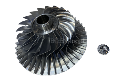
With only three-axis tools, it's not possible to make complicated aircraft holes, femoral implants, impellers, or turbine blades to the right specifications. Fixture mistakes happen with each extra setup. If you have a part with a positional tolerance of ±0.005mm, just one re-fixturing process can use up all of your tolerance funds. This risk is physically removed by 5-Axis machining part processing.
Cost and Lead Time Considerations for B2B Procurement
The rate per hour for 5-Axis machining parts is higher than the rate per hour for 3-axis machining. But if you look at the whole process, which includes the cost of the fixtures, the time it takes to set up, the number of parts that get rejected, and the cost of the labor used, 5-axis often has a lower cost-per-accepted-part for complex geometries. Lead times for prototype 5-axis parts are usually between 3 and 15 working days, and low-volume production runs are usually finished between 2 and 4 weeks.

Selecting the Right 5-Axis Machining Supplier for Accuracy-Driven Needs
The machine isn't the whole answer. Whether every order is given correctly every time depends on how the supplier handles processes, how they handle paperwork, and how they handle quality systems.
Certifications and Quality Management Systems
ISO 9001 and ISO 13485 approval are not differentiators when it comes to buying things for aircraft and medicine. They make sure that a supplier's processes are written down, can be checked, and are under control. Material traceability should be standard, not an extra request. It should be possible to follow the material from the mill certificate to the finished part.
Inspection Capabilities and Documentation
Inspection with a Coordinate Measuring Machine (CMM), surface profilometry, and material certification are the usual ways to check high-value precise parts. Every single new part number should come with a First Article Inspection (FAI) report, a package of dimensional data, and a certificate of material. Compliance risk is added to your supply chain when suppliers can't give you these papers.
Supplier Evaluation Criteria for Tight-Tolerance Projects
When checking out a possible supplier of 5-Axis machining parts, you should look at their CAM software skills, experience designing fixtures, knowledge of tooling management protocols, and their NDA/IP protection policies. All of these are normal procedures at BOEN Rapid, and they support the full NDA → technical review → FAI → production system that medical and aerospace procurement teams need.

Best Practices and Design Tips to Maximize 5-Axis Machining Accuracy
Whether a part can be held to its tolerance in production depends on the design choices that were made early on in the process.
Design Principles That Support Tight Tolerances
Titanium or stainless steel parts shouldn't have walls that are too thin. Walls thinner than 0.8 mm deflect when they are cut. Only specify the surface finish that is functionally necessary. Finishes that are too specific take longer to machine and raise the risk of tool-induced stress. If you can, make the internal radii bigger than the minimum tool radius so that the toolpath can contact efficiently.
Early Supplier Collaboration and Prototyping
Involving a machining provider in the design phase, before the plans are made public, lets DFM (Design for Manufacturability) analysis find tolerance stack-ups, material conflicts, and fixturing problems before they turn into scrap. As part of the normal project intake process, BOEN Rapid's engineering team does a DFMA review. They usually finish the first evaluations within 24 hours.
In-Process Monitoring and Precision Inspection Tools
Before the part moves on to the next feature, probing processes that run directly on the machine between operations make sure that important measurements stay within the tolerances. This in-process method, along with CMM testing and laser scanning for complex freeform surfaces, finds measurement deviations early, before it leads to a rejection of the finished part.

Conclusion
In 5-Axis machining parts, accuracy is not just one skill. It depends on how well the machine is set up, how well the tools are managed, how well the code is done, how stable the fixtures are, and how well the process environment is handled. If a procurement team is looking for high-value precision parts for medical implants, aerospace structural parts, or other similar items, knowing about these factors will help them write specifications and choose suppliers. If all the factors are managed by a supplier with the right licenses, inspection tools, and engineering knowledge, tolerances of ±0.005mm are normal and can be repeated. They are not exceptional.
FAQ
1. Does tool wear significantly affect dimensional accuracy?
Yes. As a cutting edge wears, it generates more heat and lateral force, both of which shift finished dimensions. For titanium and hardened stainless steel, tool wear progresses faster than in aluminum. Suppliers managing tight-tolerance work monitor tool life per part and replace tooling at defined intervals, not simply when a tool fails.
2. Is ±0.005mm tolerance achievable on titanium parts?
It is achievable with the right combination of machine calibration, tooling strategy, fixturing, and environmental controls. BOEN Rapid routinely produces titanium Grade 5 and 17-4PH stainless components to ±0.005mm tolerance with full CMM documentation.
3. What lead time should I plan for custom precision components?
Prototype parts typically deliver in 3–15 working days depending on geometry. Low-volume production runs are generally completed within 2–4 weeks. Complex parts requiring FAI documentation may add time for inspection and reporting.
4. What documentation comes with precision machined parts?
Standard documentation includes material certifications (with heat/lot traceability), CMM inspection reports, surface finish data, and FAI reports for new part numbers. NDA agreements and export compliance documentation are available as required.
Get Precision 5-Axis Machining Parts From a Certified Manufacturer — BOEN Rapid
BOEN Rapid provides certified 5-Axis machining parts for medical, industrial, and aerospace uses. These parts have tolerances of ±0.005mm, are fully inspected by a CMM, and can be traced back to the raw materials they came from. As a reliable company that makes 5-Axis machining parts, we offer NDA protection, FAI paperwork, and fast prototyping in 3–15 business days. Send your plans to our engineering team at contact@boenrapid.com to get a professional review.
References
1. Altintas, Y. Manufacturing Automation: Metal Cutting Mechanics, Machine Tool Vibrations, and CNC Design. Cambridge University Press, 2012.
2. Tlusty, J. Manufacturing Processes and Equipment. Prentice Hall, 2000.
3. International Organization for Standardization. ISO 10791-6: Test Conditions for Machining Centres — Part 6: Accuracy of Speeds and Interpolations. ISO, 2014.
4. Ramesh, R., Mannan, M. A., & Poo, A. N. "Error compensation in machine tools — a review." International Journal of Machine Tools and Manufacture, 2000.
5. Shaw, M. C. Metal Cutting Principles. Oxford University Press, 2005.
6. Boothroyd, G., Dewhurst, P., & Knight, W. A. Product Design for Manufacture and Assembly. CRC Press, 2011.